

Williams Technologies +1 281-402-3512 www.williamstechnologies.tech info@williamstechnologies.tech
A Williams Technologies Seasonal Advisory
As North America enters the cooling season, the HVAC industry once again faces a familiar challenge: high demand, expanding system complexity, limited field resources, and the growing pressure to restore comfort quickly and correctly.
Today’s systems are no longer simple contactor-and-capacitor equipment. Modern residential and light commercial HVAC now includes inverter-driven compressors, communicating controls, smart thermostats, electronic expansion valves, Wi-Fi integration, onboard diagnostics, sensor networks, and increasingly sophisticated fault logic. These innovations improve efficiency and comfort, but they also raise the level of technical skill required for proper diagnosis, repair, and commissioning.
At the same time, many contractors, facility teams, and service organizations continue to deal with a shortage of experienced diagnostic personnel. Peak-season call volumes rise quickly, while troubleshooting time per call often increases because newer equipment demands deeper product knowledge and more precise interpretation of operating data.
Last season also showed another industry-wide pressure point: replacement part delays. When boards, motors, sensors, inverter modules, communication harnesses, or proprietary controls are not immediately available, equipment downtime can stretch from inconvenience into serious operational disruption. In many cases, the difference between a same-day resolution and a prolonged outage is not only whether a part is available, but whether the original diagnosis was correct in the first place.
This is where expanded and early engagement of independent remote technical support becomes critical.
Remote technical support helps bridge the widening gap between customer need and field response capacity. It gives contractors, technicians, maintenance teams, and property operators faster access to technical guidance before jobs stall, parts are scarce, or repeat visits become necessary. It also supports less-experienced technicians in the field who may be capable mechanically, but need advanced assistance interpreting controls, sequences of operation, fault history, electrical values, thermistor logic, airflow behavior, or refrigerant-side symptoms.
In practical terms, remote support can help:
1. Reduce misdiagnosis. A wrong diagnosis wastes time, labor, and parts. Early technical review helps narrow faults before unnecessary replacements are made.
2. Improve first-visit effectiveness. When technicians have live remote support, they can verify test points, control logic, wiring, sensor values, and the sequence of operation while on site. We read the manuals, we study the schematics, match equipment for compatibility, verify specifications, confirm test results, and increase the technician’s assertion of the diagnosis
3. Support newer inverters and communication systems. These systems often require brand-specific logic and a stronger understanding of fault codes, boards, sensors, and communication architecture. We continue to research equipment updates, thereby allowing technicians to complete more repairs. Once the model and serial numbers are known, we begin the necessary tasks that the technician would have to perform on arrival.
4. Help manage part-delay conditions. When parts are delayed, remote support can often help determine whether temporary operating strategies, control adjustments, or further confirmation steps are possible. We can locate the closest location and availability of replacement parts.
5. Expand capability without expanding payroll. For many smaller contractors and independent technicians, remote technical support acts like an extended engineering and diagnostic desk without the overhead of staffing one full-time internally.
6. Protect customer relationships. Homeowners and facility clients expect answers quickly. Even when a repair cannot be completed immediately, clear technical direction builds confidence and trust.
The need is especially important now, at the start of the season. Once temperatures rise fully and daily demand spikes, service departments become overloaded, callbacks increase, phone queues grow longer, and technical decisions are often rushed. The best time to secure technical backup is before the emergency wave begins, not after. Some technical support calls could be delayed for days, and we are available after hours, weekends, and holidays
That is why Williams Technologies is positioned to help fill this gap, and we have highly experienced technicians to perform repairs who are Licenced and Insured.
Williams Technologies supports the industry through independent remote technical support, technical advisories, troubleshooting guidance, and HVAC system insight across a broad range of platforms and applications. This includes support for evolving equipment technologies, field diagnostics, system interpretation, service planning, and technical decision-making during periods of high demand and limited resources.
In an environment where equipment is more advanced, labor is stretched, and delays can multiply quickly, early technical engagement is no longer optional—it is a strategic advantage.
Bottom Line
The cooling season does not only bring heat. It brings pressure on technicians, contractors, supply chains, and customer expectations. The companies and individuals who prepare early, align support resources early, and use remote technical expertise effectively will be in a far stronger position to serve customers and reduce downtime.
Do not wait for peak-season overload to expose the gap. Fill it early.
Williams Technologies Independent HVAC Technical Support & Advisory Services Phone: +1 281-402-3512 Web: www.williamstechnologies.tech Email: info@williamstechnologies.tech
Partner Stalwart HVAC TACLA42992C
Williams Technologies Field Paper
Testing Thermistors in HVAC and Refrigeration Systems
Common Resistance Behavior, Ice-Water Benchmarking, and Why Every Service Technician Should Carry an Ice Cooler
Prepared by Williams Technologies
Jules W. Birmingham
Phone: 281-402-3512
Email: info@williamstechnologies.tech
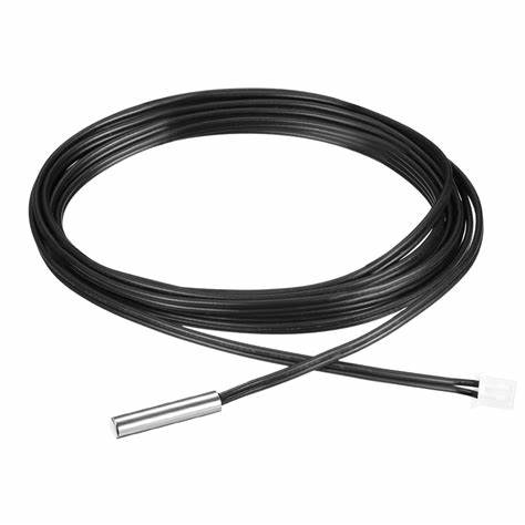
Thermistors are among the most important sensing components used in modern HVAC, refrigeration, heat pump, VRF, mini-split, chiller, and control systems. They provide the control board with temperature information needed to manage compressor operation, fan control, defrost, discharge protection, coil protection, room temperature sensing, and many other operating functions. A failed thermistor, an out-of-range thermistor, a sensor with drift, or a wiring problem associated with the sensor can cause poor performance, nuisance lockouts, false error codes, freeze-up, overheating, or complete system shutdown.
For that reason, technicians should be comfortable testing thermistors both in the field and on the bench. One of the most reliable and practical reference methods is the use of ice water as a temperature benchmark, because a properly prepared ice-water bath provides a stable and repeatable temperature point very close to 32°F (0°C). This gives the technician a known condition against which the thermistor can be checked.
Most HVAC thermistors are negative temperature coefficient (NTC) devices. This means that as temperature rises, resistance falls. This is the most common type found in indoor air sensors, coil sensors, discharge pipe sensors, suction thermistors, and outdoor ambient sensors. Less commonly, some systems may use positive temperature coefficient (PTC) sensors, where resistance rises with temperature, but NTC thermistors dominate HVAC equipment.
When testing a thermistor, the first rule is to identify the expected sensor type and its resistance curve. A thermistor is not judged only by whether it has continuity. It must be compared to the expected resistance at a known temperature. A sensor may still show resistance and yet be inaccurate enough to create serious control problems.
A typical NTC thermistor behaves as follows: resistance is higher at low temperature, moderate at room temperature, and lower at high temperature. Depending on the manufacturer, many common HVAC thermistors are built around nominal values such as 5 kΩ, 10 kΩ, 15 kΩ, 20 kΩ, or 50 kΩ at 77°F (25°C). The exact value depends on the equipment design. Because of this, technicians should never assume all thermistors have the same room-temperature reading. Always compare the measured value to the manufacturer’s chart whenever available.
As a practical example, a 10 kΩ NTC thermistor commonly measures around 10,000 ohms at 77°F (25°C), but at 32°F (0°C) the same sensor will usually measure substantially higher, often in the range of roughly 27 kΩ depending on the curve. A 5 kΩ NTC thermistor will likewise rise well above its 77°F value when placed in ice water. The exact number matters less than matching the reading to the correct resistance-temperature chart for that sensor family. The point is that the ice-water test gives the technician a dependable low-temperature reference.
A proper thermistor test should begin with safety and isolation. Disconnect power to the equipment where appropriate, isolate the sensor from the control circuit when possible, and measure the thermistor directly at its leads or connector. Measuring through the board can create misleading readings because of parallel circuit paths or board bias voltage. Always inspect the connector, harness, and sensor mounting point before condemning the thermistor itself. Many apparent thermistor failures are actually caused by poor connections, corrosion, moisture intrusion, rubbed wires, or loose terminals.
For a bench test, the technician should prepare a small container of crushed ice and water. The goal is not just cold water but a true ice-water mixture where the sensor tip is surrounded by slush-like water and ice. This produces the most stable 32°F reference. If the container contains only cold water without enough ice, the temperature may rise above the intended test point and the reading will be less reliable. The sensing portion of the thermistor should be immersed while keeping wire splices or unsealed connection points out of the water unless the sensor is specifically designed for full immersion.
The technician should allow enough time for the thermistor reading to stabilize. Resistance may shift for a short period while the sensor equalizes to the bath temperature. Once stabilized, the measured resistance should be compared to the manufacturer’s chart for 32°F. If the reading is significantly outside tolerance, the thermistor may be defective or drifting. If the reading is correct in ice water but not correct when reinstalled, attention should turn to location, mounting, airflow influence, pipe contact quality, insulation over the sensor, or harness problems.
Ice-water testing is especially useful because it helps remove guesswork. Ambient temperatures in shops, vans, attics, rooftops, and mechanical rooms vary too much for “room temperature” testing to be a dependable standard unless the actual air temperature is measured carefully. Ice water provides a repeatable known point. In the same way that a technician uses a reference voltage or a known pressure relationship, the ice-water bath provides a known thermal reference.
For field service, it is good practice for technicians to carry a small insulated ice cooler as part of their diagnostic kit. This may seem simple, but it is extremely useful. A cooler allows the technician to maintain a consistent testing method while traveling between calls. When used with a digital thermometer and an ohmmeter, it becomes a practical diagnostic standard. A small cooler can also protect temperature-sensitive materials, help verify other sensors, and support repeatable troubleshooting when a service call involves intermittent sensor-related faults.
The relevance of carrying an ice cooler is not convenience alone. It is about accuracy, repeatability, and professional diagnostics. Too many sensors are replaced based on suspicion rather than measured verification. A technician with an ice cooler, a resistance chart, and a quality meter can determine whether the sensor truly matches expected behavior. This reduces unnecessary parts replacement, prevents callbacks, saves labor time, and improves confidence in the diagnosis.
Thermistor testing should also include dynamic behavior. A good sensor should change resistance smoothly as temperature changes. If the resistance jumps, opens intermittently, or becomes unstable when the wire is flexed, the sensor or harness may be failing even if the static reading appears close. A simple warm-hand test after the ice-water test can confirm that the resistance moves in the expected direction. For an NTC sensor, resistance should fall as the sensor warms. If it does not respond smoothly, further investigation is required.
Technicians should also remember that proper sensor mounting is critical. A perfectly good pipe thermistor may report bad data if it is not firmly attached to the pipe, if the clip is loose, if the sensing bulb is shifted, or if the insulation is missing. Likewise, an air thermistor installed outside the intended airstream may mislead the board and create operational problems that mimic a failed sensor. Therefore, thermistor testing is never only about the ohms reading. It is also about installation quality, sensor location, and circuit integrity.
In summary, thermistors are precision temperature-dependent resistors that should be tested against known values, not assumptions. Most HVAC systems use NTC thermistors, which increase in resistance as temperature drops and decrease as temperature rises. Because each thermistor family has its own resistance curve, manufacturer data should always be used whenever possible. Ice water provides one of the best field and bench reference temperatures available to technicians, and carrying a small ice cooler is a practical, low-cost, high-value way to improve diagnostic accuracy. This simple habit supports better troubleshooting, fewer wrong parts, stronger technical credibility, and better customer outcomes.
Service Reminder
When checking thermistors: isolate the sensor, verify the actual test temperature, compare resistance to the correct chart, inspect the harness and connector, confirm mounting quality, and use an ice-water bath whenever a known low-temperature reference is needed.
Technical Note
Resistance values vary by manufacturer and sensor curve. Always confirm the exact resistance-temperature relationship from the equipment service literature before condemning a thermistor.
Disclaimer
This paper is intended for technical guidance only. All testing should be performed using manufacturer procedures, approved safety practices, and proper electrical isolation methods.
Modern Thermistors and Smart HVAC Sensing vs Legacy Technologies Efficiency, Serviceability, Reliability, Affordability
Modern HVAC equipment does far more than turn on, satisfy a thermostat, and shut off